To assist you with precise equipment integration and console programming, this page details the action logic of each internal switch contact across different operational strokes.
How to Read the Diagram?
This diagram is a standard Contact Closure Diagram, providing a visual representation of the joystick’s electrical state during movement.
- Horizontal Axis (Operational Stroke): Represents the full stroke of the joystick from one side to the other, divided into five zones: far-left, left, neutral, right, and far-right.
- Vertical Axis (Contact No.): Identifies the integrated switch contact numbers (Contacts 1 to 9) inside the joystick.
- Black Blocks: Indicate that the corresponding contact is in the closed (ON / Closed) state at that operational position.
- White Blocks: Indicate that the corresponding contact is in the open (OFF / Open) state at that operational position.
Contact Action Table
Note: The following instructions apply to joystick models supporting the 1-9 contact array configuration. For custom timing requirements, please contact technical support.
| Contact Closure Diagram | Contact No. | Action Logic Description |
|---|---|---|
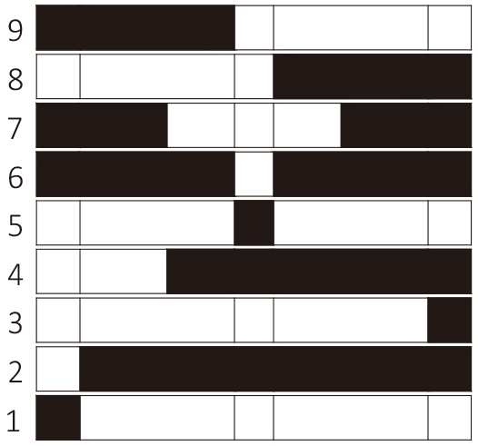 |
9 | Closed throughout the left side. |
| 8 | Closed throughout the right side. | |
| 7 | Open in and around neutral, closed at both ends of the travel. | |
| 6 | Open only in the neutral position; closed elsewhere. | |
| 5 | Closed only in the neutral (center) position. | |
| 4 | Closed from just before neutral to the end of the stroke. | |
| 3 | Closed only in the far-right position. | |
| 2 | Closed in all positions except far-left. | |
| 1 | Closed only in the far-left position. |
Typical Application Scenarios
Properly utilizing contact combinations can significantly simplify logic programming for PLCs or underlying control boards.
1. Neutral / Safety Interlock
- Contact 5: Functions as a strict Zero Interlock signal, ensuring continuity only when the joystick is completely untouched and centered, ensuring equipment safety during standby.
- Contact 6: Functions as an Off-Normal / Action signal, triggering as soon as the joystick leaves the center deadband, commonly used for bus wake-up or parking brake release.
2. Directional Control
- Contacts 8 & 9: Serve as standard bi-directional logic switches. Contact 9 triggers reverse or leftward drive, while Contact 8 triggers forward or rightward drive.
3. End-of-Travel / Unlock
- Contact 1: Used for specific boundary logic, such as confirming the “pull all the way back” anti-accidental zero-unlock mechanism on the Brake Joystick.